| Elphel camera under the hood: from Verilog to PHP |
by Andrey N. Filippov (Jan. 13, 2009)
Foreword: ... Enjoy . . . !
Elphel camera under the hood: from Verilog to PHP
by Andrey Filippov
Background
When I started Elphel in 2001 I was inspired by effectiveness of the FOSS witnessed from my colleagues (I did not know anything about GNU/Linux before that).
I then bought the idea of having to develop only the new things and reusing whatever others already did before me. The same
"Standing on the Shoulder of Giants" metaphor that was already proven in science, method that is probably the most powerful instrument of the human minds.
I immediately wanted to apply this approach that already gained momentum in the software world to the hardware devices I was developing through most
of my career. I also considered it as a good business opportunity because while being a user of camera systems myself many times I encountered the same problem.
Off-the-shelf products are often very close to your requirements, but do not have the exact match. And it is usually difficult if not impossible to make that last step,
modify or improve otherwise a good product.
And yes - it did work even better than I expected, in just about 3 months there was the first generation model 303 camera running GNU/Linux and borrowing
functionality from the operating system itself, other free software included in the software distribution (Axis Communications SDK) and another applications that I ported to this CPU architecture (arch/cris) myself.
Of course some code still had to be written but that was only the one specific to the brand new hardware nobody but me had ever had before. And this newborn camera
already had more functionality that I could make in a year of developing a ground-up in-house system.
Being a hardware manufacturer we have an advantage over the pure software projects that we can make profit selling tangible goods, but there is the other side of that
feature. We have smaller developer community because an active developer has to have actual hardware that is more expensive to "duplicate". We are also
developing new products and providing support to the existent customers. This and the fact that the freedom (and so flexibility and possibility to
customize) of our designs is itself of a value for our customers, allows us to keep all our hardware designs free as in software (they are provided with either
GNU GPL or GNU FDL licenses). Early in 2004 we started a project at Sourceforge
and since then it is Elphel software repository both for the distribution to our users and team collaboration, all Elphel software and FPGA code is released under
GNU GPL v3.0 and the same code we use internally is available for download and in the CVS repository for any GNU GPL compliant use.
From the very beginning we were trying to make developer-friendly, customizable products, experimented with different technologies - you can find their descriptions
in the previous publications in LinuxDevices listed at the end of this article. Most such experiments proved viability of the technologies used and the camera project
was growing incrementally, accommodating new sensors and other electronic components, adding more features to the FPGA and the software code. In parallel we were gaining
experience in designing network cameras that combine power of the free software running in the general purpose CPU with the performance and flexibility of the "hardware"
processing implemented in the reconfigurable FPGA using the GPL-ed code written in Verilog HDL. And as the project was growing I was getting stronger temptation to
redesign the core software that runs in the camera and put the ideas we got while working on the cameras into its foundation. And last year we did it - re-wrote the key
parts of the FPGA code and the camera software to make it what I believe it should be. Below I'll describe the current state of the camera project and how the current
software release (8.0) differs from the previous ones. It is Elphel camera that is described below, but I hope this article may help other camera developers who are now
on the same early project stage themselves as I was 7 years ago to use our experience and skip some of the intermediate stages we went through.
Camera hardware architecture
Starting with the first camera (model 303) developed at Elphel in 2001, and especially when we used Xilinx reconfigurable FPGA
a year later the overall camera architecture remained stable. It was designed to be flexible to accommodate different sensors and extension boards,
the main system board is essentially a universal computer running GNU/Linux with addition of the FPGA and a dedicated video buffer memory.
FPGA is used for image processing and compression (and does it much faster than the CPU), it is also used for interfacing sensors and daughter boards,
simplifying support of the devices that were not yet available at the time when the system boards were designed and manufactured. Block diagram of a
typical Elphel camera includes camera processor board (10353), CMOS sensor front end (10338), optional I/O extension board (10369) with adapter boards (103691,103692).
Other configurations may include CCD sensor front ends, mechanical shutter control, additional FPGA processing/multiplexer boards. Either universal
I/O extension board or just smaller sync boards can be used to lock (synchronize) multiple cameras for stereo or panoramic applications.
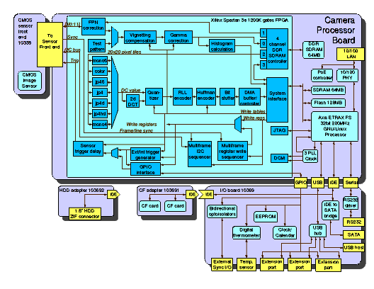
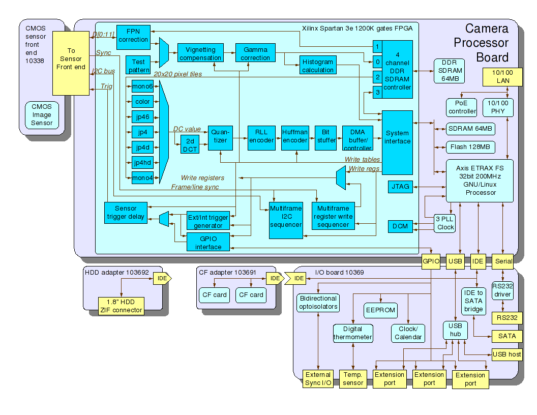
Elphel model 353 camera: hardware and FPGA layers
(Click to enlarge)
The diagram shows camera main hardware components, I/O ports and internal connections between the boards. It also includes details about the major processing
modules implemented in the FPGA - the intersection of the hardware and software domains.
Code layers in the camera
Software that runs in the camera spans multiple layers in overall system hierarchy and combines code developed at Elphel with the other free software.
We use KDevelop IDE to navigate through all this code, compile and build drivers and applications, launch FPGA code simulation and generate the camera
flash image ready to be installed. Only the "silicon compilation" - generation of the FPGA configuration file from the source code is handled by a separate
software (non-free but free for download) - Xilinx WebPack.
- Verilog HDL code in the FPGA performs most computationally-intensive tasks in the camera, it handles all of the image processing/compression
operations providing compressed bitstream ready to be sent over the network or recorded on the storage media. The compiled FPGA images are conveniently
loaded by the CPU through its GPIO pins connected to JTAG port of the FPGA - that can be done unlimited number of times so for example it is easy to add 'printf'
equivalents to the code while troubleshooting. Contrary to the software code run by the CPU the Verilog code statements are compiled to the different
physical parts of the chip and are executed in parallel. And so there is virtually no performance penalty when adding more code as long as there are
some FPGA resources left. FPGA code directly interfaces the sensor front ends (usually through I2C bus for the sensor commands and parallel data in
for images) and optional extension boards, it includes multichannel external DDR SDRAM controller for the dedicated video buffer memory. It shares
system bus with the CPU, communicates with the CPU software in the PIO mode (to read/write control registers, write table data) as well as in DMA mode
for transferring compressed frames to the system memory. Current (8.0) software supports scheduling of the internal register writes as well as sensor
i2c commands so that they are activated for the specified frame.
- Kernel drivers make up the next overall software layer in the camera (and the lowest one of the code that is running in the CPU). These drivers
supplement the standard ones (i.e. network, IDE, USB) and provide software interface to the FPGA modules (i.e gamma correction, histograms, color converter,
compressor) and external devices (like image sensor) connected to the FPGA. As the main camera function is to stream or record video that can run at high
frame rate, the related drivers are designed to ease the real time requirements to the application layer software. Such drivers rely on the interrupts
generated by the FPGA code for each frame transferred from the sensor and/or compressed and stored in the system memory. Software makes use of the
"hardware" command queues (Multiframe I2C sequencer, Multiframe register write sequencer) implemented in the FPGA as well as
a large output buffer for the compressed video. Such command/data buffering facilitates camera control and video data handling by the CPU software and
synchronizing with the stream processing in the FPGA, making applications tolerant to pauses caused by I/O events (i.e. waiting for the mass storage device)
or just long calculations.
- Application layer consists of standard programs like Busybox collection, web, ftp, telnet and ssh servers. There are also camera-specific applications,
such as:
- imgsrv - fast image server that avoids extra memory copying and serves JPEG (including multi-part ones) images directly from the circular video
buffer to HTTP GET requests. It also implements buffer navigation (buffer holds several seconds of full frame rate video) and Exif image meta data
browsing (including GPS and compass data if attached).
- camogm - application for recording video (and audio if USB audio adapter available) to any of the attached mass storage devices, like Compact
Flash cards, SATA (or 1.8" ZIF) HDD. It uses system circular video buffer and makes sure there are no frame drops, i.e. when closing previous and
opening the next file in a sequence. The program runs as a daemon accepting commands over the named pipe, can be integrated into web applications as
camogmgui.
- str - unicast/multicast RTSP videoserver capable of streaming full sensor frame video (plain RTP has a limit of 2040 pixels for image width or height),
the stream can be rendered with such media players as MPlayer or VLC (provided they use current live555 library and include current improvements that
overcome earlier restrictions on the frame size). Streamer can work in "nice" mode when used as a viewfinder while video is recorded with camogm,
skipping frames to prevent recorded frame drops if the CPU resources are insufficient. It is designed to tolerate short frame size changes, making it
possible to reprogram sensor and acquire a full resolution snapshot while simultaneously streaming lower resolution (but higher frame rate) video.
- autoexposure - a daemon running in the camera that uses histograms calculated by the FPGA code inside a specified sub-window of the image frame
to automatically adjust sensor exposure time and white balance. It has multiple programmable parameters to achieve flexible regulation suitable for
particular application, most of these parameters can be adjusted through the camvc AJAX web GUI.
- Web applications and scripts. Being network devices Elphel cameras always relied on web interface for operating them, such as described in
"AJAX, LAMP, and liveDVD for a Linux-based camera", but that was only
after the last system upgrade to the model 353 (full cameras timeline is available on Elphel Wiki)
that included the faster CPU (ETRAX FS) and 64MB of system memory when we decided to use scripting language for the top layer of the camera software.
For that purpose we replaced Boa (web server that was provided in Axis SDK) with Lighttpd known to work
nicely with FastCGI that we needed to run PHP efficiently. This technology allows
several copies of the PHP to be running ready to serve HTTP requests, interpreter (>2MB in the camera) does not needed to be re-started for each new one.
As we primarily target our products to the users who would likely want to customize them to their specific applications we looked for the scripting language that is easy
to use, efficient and is already familiar to many developers - that was why we decided in favor of PHP
(Tiobe Index).
PHP is very well documented on the php.net web site where the official reference is supplemented by multiple user-provided real life examples, it is definitely possible
to start writing working code (including the code running in the cameras) the first day you tried it. Execution efficiency is achieved by abundance of dedicated functions
to handle many of the programmer's tasks in a single call - both included with PHP itself and provided separately as extensions. At Elphel we also made use of
such approach by providing camera-specific extension functions that allow easy access to the low-level and hardware functionality without the penalty of being too slow
to be useful for embedded application. When starting with writing PHP extension to run in the camera I used a nice online tutorial by Sara Goleman
Extension Writing Part I: Introduction to PHP and Zend (there is also a book "Extending and
Embedding PHP" written by the same author).
As the camera project is a work in progress, and both hardware (FPGA Verilog code) and drivers may change after some PHP programs are already created, we made
particular considerations to synchronization between different layers of the software. Parameter definitions in the driver code are exported as PHP constants and their
symbolic names are available throughout the extension functions. In addition to the individual names of the 32-bit parameters defined in the driver header file extension
handles composite names that include optional offset in the register file (i.e. hardware-specific CMOS sensor registers) and bit-field selection.
There are multiple scrips installed in the camera that are accessible through the lighttpd web server (with FastCGI), including those designed to be part of AJAX
applications, others just provide access to the camera hardware (like I2C bus to clock/calendar, identification EEPROM, thermometer). Many of the scripts are
intended for development - from creating control interfaces to fine-tuning of the driver parameters, monitoring internal data structures and profiling the
interrupt service routine. And of course it is easy to create and upload (or is it download in this context?) custom script to the camera - both to the camera RAM-disk
(tmpfs) to safely try them or to the camera flash memory - to stay longer survive power cycles.
In addition to be used as a back end for web applications PHP is as also used in CLI mode, powering multiple hardware initialization scripts such as for reading I2C
devices, discovery of the FPGA add-on boards using their JTAG port, preparation of the Exif templates for the images/video that match camera hardware capabilities and
optional peripherals (compass and/or GPS modules). In this capacity such scripts partially replace regular shell scripts. I believe the PHP code is easier to read,
understand (and modify, of course) than shell scripts for for many people who are not professionals dealing with the shell scripts regularly. I know that professionals,
on the other hand, can often write shell scrips smaller and more efficient, but for me it usually takes too much time reading manuals and googling for examples to write
just a few lines of the nice shell code.
New features of the camera software
The software running inside Elphel cameras (including the FPGA code) survived multiple upgrades of all of the major hardware components: CPU, FPGA, memories and Ethernet PHY.
It was growing incrementally and included support for the new hardware (i.e. more sensors that became available) and additional processing modes, but the basic operation did not change.
Last year (2008) we implemented several changes to the code running in the cameras. First step (it actually started a year earlier) was to separate reading of the video circular
buffer (used when serving images and video over network, recording to mass storage devices) from controlling the camera video frames acquisition to the buffer that is subject to
hardware dependent conditions and frame latencies. That was the first step to implement support of the pipeline operation of the camera modules, several applications were
created that made use of the new operation of the video buffer. Next stage involved major redesign of the frame control/acquisition part of the camera operation that,
together with the additional modes of the color processing made up the core of the new 8.0 software that is now used with the cameras.
- Camera control tailored to the pipeline operation
Driver in the earlier software supported two sets of acquisition parameters imageParamsW[ ] - parameter values requested by applications (validated and modified by the driver
to the nearest value
supported by the hardware) and imageParamsR[ ] - array of parameters currently used by the driver. When application (usually it was ccam.cgi - a CGI program called from the web server) wanted to
change some acquisition parameter(s) it changed elements of imageParamsW[ ] array and then called a driver function to program sensor and/or compressor. Most parameters had
several frames latency (from the moment parameter was changed until the influenced image was registered in the system memory) so that programming function had to use
interrupts and application had to be able to wait for the requested image to become ready.
Such model was working good enough when everything was programmed once and then just new images (or frames in a video stream) were acquired with the same settings. It was possible
to change some parameters on the fly - (i.e. exposure or analog gains that did not disturb the following pipeline of the camera data processing:
sensor registers setup ->
sensor video frame out ->
FPGA image preprocessing ->
video frame buffer ->
FPGA compressor ->
DMA ->
system memory ->
frame output
Most other parameters even sensor window of interest (WOI) vertical pan often caused sensor to output corrupted frame and the pipeline operation was also interrupted.
Earlier software could not handle propagation of related changes through the pipeline as it was only aware of "requested" and "actual" values pair for each parameter.
The real-life change of the parameters (image WOI height or similar) involved more stages: sensor register change, FPGA pre-processor height change, video buffer write
controller and video buffer read controller re-programming, compressor number of tiles change, output JPEG image height (in the header) change - all happens at different time,
with different frame latencies. The software learned how to handle some
specific cases, but often the only way to change some of the acquisition parameters was to shut everything down, reset FPGA memory controller, compressor, reprogram them
and re-start the pipeline operation. That caused multi-frame interruptions, the output video buffer had also to be reset (as FPGA source could be reset after sending out
unknown part of the frame) and that influenced all the applications that relied on that buffering.
The 8.0 software redesign from the very beginning was targeted to support pipelined operation of the camera hardware and FPGA modules in order to eliminate the need of the
acquisition restart and minimize the number of the lost frames. Instead of having just two values per parameter this software maintains individual parameters for each frame -
they are set by applications in advance so driver has time to resolve possible parameter dependencies and to compensate for the latencies in all of the pipeline stages.
In the actual implementation there just eight parameter values maintained by the driver - six frames in the future, current and previous frame, subset of the parameters is
copied to the deeper buffer so that data is preserved longer after the particular frame acquisition.
Applications write acquisition parameters for the specified frame through the driver write() calls and such calls are atomic making sure that all the parameters written are
applied to the same frame. Many of such parameter modifications involve scheduling actions that are evaluated by the driver when serving frame interrupts. Driver
uses parameter action tables for such scheduling, these tables are both compiled in the driver and are still available for editing at run time through the web interface.
This feature is convenient for the software development, for the code modification to accommodate the new hardware. Each action has a related latency - number of frames
between the related commands are sent to the sensor (or applied to the FPGA modules) and the first influenced by this action frame appears in the output circular video buffer.
The action latency tables (they are different for free running and externally synchronized sensor) are provided similarly to the action table - both as compiled in constants
and run-time edited through web interface parameters.
There are 32 different actions implemented in the software (so a single 32-bit word can be used to specify all actions needed for the frame), each of them includes
image sensor-agnostic function that deal only with FPGA and software that is common for every sensor front end. Such function is optionally followed by a sensor-specific
one that is dynamically linked during sensor identification, so only the sensor-specific functions are needed to be added for each new sensor front end.
Scheduled actions are processed by the the driver during once-per-frame interrupts, at least latency (as defined above) frames before the target frame (frame that is
to appear at the output with new parameters applied). Additional programmable parameter specifies how many frames ahead of the last possible frame is the driver allowed
to execute the actions. Doing this ahead of time makes the driver tolerant to missing interrupts (that could happen at very high FPS with small WOI and many parameter
changes applied to the same frame), it uses the hardware command queues. Each action involves validation of the input parameters and their modification if they are not
compatible with the hardware capabilities or other imposed restrictions, in that case the modified parameters can also trigger more actions.
Parameter validation is normally followed by the calculation of the hardware register values that are needed to be sent to the sensor and FPGA modules, and finally these
values are written to one of the hardware command queues.
The command queues are implemented in the FPGA (Multiframe I2C sequencer, Multiframe register write sequencer in the block diagram). Every one of the two
sequencers can store up to 64 commands in each of the seven individual queues: for the current and the next six frames and then output them (to the sensor and internal
FPGA modules, respectively) right after the beginning of the scheduled frame in the sensor (commands for the current frame are sent out immediately).
Read access to the driver parameters does not involve any actions as write access does, so it is implemented as memory mapped array accessible from the applications, including
PHP. This program opens the related files and maps the data arrays during initialization and as it is configured to work in FastCGI mode many HTTP requests
are served without re-initialization of the driver data access. Parameter symbolic names defined in the driver header file are exported to the PHP extension as PHP constants,
extension functions are able to process array arguments with the key names automatically derived from the driver parameters names. The PHP extension functions use driver write() function
to set the camera acquisition parameters and direct mmap() function to read them. Driver also maintains an array of global parameters that are not linked to the particular frames and
do not cause any actions when being written to. Those parameters are accessible with mmap() for both direct reading and writing, other extension functions use similar access to
other driver structures, such as gamma tables used for pixel data conversion and image histograms calculated in the FPGA.
- Color processing in Elphel cameras
This section describes several modes of handling color information used in Elphel cameras. These modes offer additional options of balancing between image quality and compression ratio
and between realtime in-camera color processing compatible with the standard viewers and post-processing using the host computer that results in higher quality of the images
recorded with the regular sensors that have color mosaic filters.
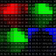
Most of the color images sensors (including those used in Elphel cameras) rely on a Bayer pattern filters so
each pixel can only detect a single color of the three RGB as shown below:
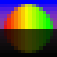
Actual image - data that reaches the sensor |
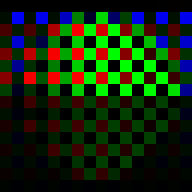
Image data that gets to the sensor pixels through the Bayer color filters |

Same data with the visible color removed - anyway each pixel is monochrome as it can detect only a single color |
Image registration by the sensor through the Bayer color mosaic filters
(Click to enlarge)
|
It may seem that a lot of information is lost (2/3 if only one of three color components is left in each pixel) but modern algorithms can restore missing color
components with good precision. High quality algorithms use multi-pass calculations and need information from the pixels far from the one where the colors are
to be interpolated. Such processing is a challenge to implement in the FPGA as the data transfer between the FPGA and external buffer memory (on-chip resources
are not enough to hold the high resolution video frame) can be a natural bottleneck. Elphel cameras use much simpler processing the data for JPEG compression
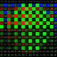
comes from the buffer memory formatted as 20x20 overlapping tiles so that each tile corresponds to one 16x16 pixel macroblock (MCU) for JPEG compression as YCbCr 4:2:0.
This mode means that for each 16x16 pixels there will be four of 8x8 pixel blocks to represent intensity (Y) and two additional 8x8 blocks to encode color. Color is
represented as Cb (difference between blue and green) and Cr (difference between red and green), each having half spatial resolution in both vertical and horizontal
directions compared to the original pixels (and Y component).

|

Y0 |

Y1 |

Cb(4) |

Cr(5) |

Y2 |

Y3 |
| sensor Bayer data |
Six 8x8 pixel blocks ready for compression - 4 intensity (Y) blocks and 2 differential color components (Cb and Cr) |
Color processing to convert Bayer pixel data into color YCbCr 4:2:0 ready for JPEG or Ogg Theora compression
(Click to enlarge) |
Additional pixels in the tiles (2 rows from each of the four sides) are provided by the memory controller to interpolate pixels near the edges of the 16x16
macroblock that allows to use 5x5 pixel areas to calculate each of the macroblock pixel's missing color components, but the current code uses only simple
3x3 bilinear interpolation disregarding the outmost pixels. This code combines Bayer pattern interpolation and RGB->YCbCr conversion in a single step, result
values for Y, Cb and Cr are calculated directly from the input Bayer data as illustrated by the image above.
If you click on that image (and similar images below) to enlarge it, hovering mouse pointer over pixel block will show coordinates, values of the pixels, and how
they are calculated. You may also try the PHP script used to generate those images and apply it to the other
samples (including your own ones).
Such simple color processing works good enough for many video monitoring applications, but produces unacceptable color artifacts when the object contains sharp
gradients - that is the case during document scanning. Other video applications also do not require real-time availability but need the best image quality hardware
can provide (i.e. filming). In both cases it would be nice to have raw pixel data but that requires higher bandwidth of the data transmission (in our case limited
to the 100Mbps of the available Ethernet connection) or recording.
We needed to provide raw Bayer data while maintaining acceptable frame rate on our previous model 323
camera were network speed was additionally limited by the on-chip MAC of the earlier Axis ETRAX 100LX processor - there were two network connectors and two of the 10313
boards operating in parallel to increase overall data rate. It was then when I tried to modify the already implemented JPEG compression chain and to reuse the developed
code and make it suitable for the Bayer data compression. Of course it was possible to just treat the Bayer pixels as if it was the data from the monochrome sensor
(the rightmost picture on the Image registration by the sensor through the Bayer color mosaic filters illustration above), but that would produce very inefficient
JPEG compression. Such compression (and many similar ones) is designed so that the high spatial frequency components are sacrificed first, as they carry the least
of the perceivable information. But if the sensor is actually a Bayer color one, not a monochrome then there is a lot of high frequency components even if there
are no sharp gradients in the image. For a colored object there will be a repetitive pattern with maximal frequency - odd and even pixels will have different values.
|
|

Y0 |

Y1 |

Cb(4) |

Y2 |

Y3 |

Cr(5) |
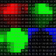
| sensor Bayer data |
Re-arrangement of the pixels that groups each color component together |
Six 8x8 pixel blocks ready for compression - 4 intensity (Y) blocks and
2 dummy differential color components (Cb and Cr) needed for compatibility
with the standard JPEG decoders |
Preparation of the sensor raw Bayer data for efficient JPEG compression (JP4 mode)
(Click to enlarge) |
How many bits are really needed in the image pixels?
Modern CMOS image sensors provide high resolution digital output, mainstream ones had 10 bits and now many have 12 bits. When CCD sensors are used, the same (or higher) resolution is provided by separate ADC or integrated CCD signal processors. That resolution is significantly higher than that used in popular image and video formats - most are limited to just 8 bits per pixel (or per color channel depending on the image format). To catch up with the sensor and provide higher dynamic range many cameras (and their users ) switch to formats that support higher number of bits per pixels, some of them use uncompressed, full (sensor) dynamic range raw data. Such formats use significantly more space on the storage devices and bandwidth for transmission.
Do these formats always preserve more of the information registered by the sensors? If the sensor has 12 bit digital output - does that mean that when using an 8-bit JPEG the four least significant bits are just wasted and to preserve them raw format is required?
In most cases the answer is "no". With the sensor technology advances the sensor pixels get smaller and smaller approaching the natural limit of the light wavelength - it is now common to have them less than 2x2 microns (i.e. in the sensors used in the mobile phone cameras). And one of the consequences of the small pixels is the reduced Full Well Capacity (FWC) - maximal number of electrons that each pixel can accommodate without spilling them out. Why is that important? - Because of the Shot Noise - variations of the number of electrons (there is always an integer number of them, there could be no ½ electron). That noise is caused by the quantum nature of electric charge itself, there is no way to eliminate or reduce it for the particular pixel measurement. This noise is proportional to the square root of the total number of electrons in a pixel, so it is highest when the pixel is almost full.
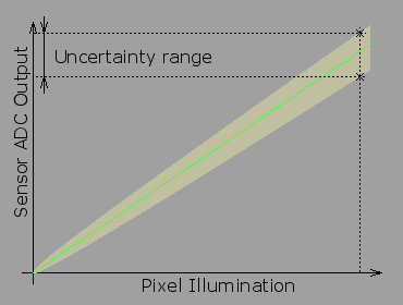
Pixel output uncertainty caused by the shot noise
If we'll try to keep track of the pixel value in ideal conditions with the same illumination, same camera settings that measured pixel value will change from frame to frame. The picture above shows that for hypothetical sensor with FWC of just 100, in the real sensors the uncertainty is smaller, but it can still significantly reduce amount of information that we can receive from the sensor. Our measurements show that a typical Micron/Aptina 5 Megapixel sensor MT9P031 with 2.2x2.2 micron pixels have FWC of ≈8500 electrons, that means that when the sensor is almost full, the pixel value would fluctuate as 8500±92 or more than ±1%. Such fluctuation corresponds to 44 counts of the 12 bit sensor ADC.
So is there any real need for such high resolution ADC when some 5-6 LSBs don't carry any real information? Yes, it is still needed because modern sensors have really low readout noise and in the darks a single ADC count is meaningful - square root of zero is zero (actually even in the dark there are some thermal electrons that get to the pixels - with no light at all). With ADC counts having different information payload for small and large signals it is possible to recode the pixel output equalizing the information values of the output counts.
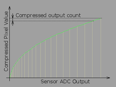
Non-linear conversion of the sensor output
This non-linear conversion assigns incremental numbers to each pixel level that can be distinguished from the previous one in a single measurement, so for small signal (in the darks) each next ADC output value gets next value, increasing to more than 40 ADC counts per number for large signals. Such conversion significantly reduces number of output values (and so number of bits required to encode them) without sacrificing much of the pixel values. The form below calculates effective number of bits for different sensor parameters and ratio of the encoder step to the noise value for that output level.
Optimal encoding and gamma correction
Luckily enough nothing has to be done to utilize the non-linear encoding optimal for maintaining constant noise to output count ratio as described above. All cameras incorporate some kind of a gamma correction in the signal path. Historically it was needed to compensate for the non-linear transfer function of the electron guns used in CRT monitors (television receivers). Cameras had to apply non-linear function so the two functions applied in series (camera+display) were providing image that perceived to have contrast close to that of the original. Most CRTs are now replaced by LCD or other displays that do not have any electron guns, but that correction is still in use. It is not just for backward compatibility - gamma correction (also called gamma compression in the camera) does a nice job of transferring higher dynamic range signal even when the signal itself is converted into digital format. Different standards use slightly different values for gamma - usually in the range of 0.45-0.55 on the camera side. And compression with gamma=0.5 is exactly the same square root function shown above, optimal for encoding in the presence of the shot noise. With this kind of gamma encoding full well capacity of several hundred thousands electrons is needed to have 12 bits of meaningful data per pixel in the image file. Such high FWC values are available only in the CCD image sensors with very large pixels.
Measuring the sensor full well capacity
Earlier I wrote that the Aptina sensors we use have FWC≈8500e-. Such data was not provided to us by the manufacturer, it is not included (at least in the openly available) documentation - we measured it ourselves. The FWC value is important because it influences the camera performance, so by measuring the camera performance it is possible to calculate the FWC. We did it with our cameras, the same method may be applied to most other cameras too. To make such a measurement you need to be able to control ISO settings (gain) of the camera and acquire a long series of completely out of focus images (with lens removed if possible, if not - completely open iris and use uniform target). ISO (gain) should be set to minimum, exposure adjusted so the area you'll analyze has pixel level close to maximal. Use natural lighting or DC-powered lamps/LEDs to minimize flicker cause by AC power. If the sensor is color - use green (with incandescent lamps - red) pixels only - they will have the minimal gain. Then measure differences between the same pairs of pixels in multiple frames (we used 100 pairs in 100 frames) and find root mean square for the differences in each pair, divide than by square root of 2 to compensate for the fact you are using differences in pairs, not the pixel values (pairs make this method more tolerant to fluctuation of the total light intensity and to some uncontrolled parameter changes in the camera). If it is possible to turn off gamma correction (as was in our case), the ratio of the pixel value to the measured root mean square of the variation will be equal to the square root of the number of electrons, if the gamma-correction can not be controlled you may assume it is around 0.5.
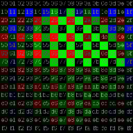
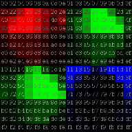
Working solution to increase compression efficiency in this case was rather simple - it was to rearrange pixels in each 16x16 macroblock so each color component pixels get into a separate
8x8 pixel block. Pixel numbers in the second (re-arranged) image show their location in the original macroblock - they are consecutive hex numbers there (you need to open enlarged image
to see the numbers). Such modification made possible efficient
compression of the raw Bayer pixel data with the otherwise standard JPEG encoding. In that original implementation we even preserved dummy color components. As they
consist of all zero values compression is very efficient and the file size does not increase much, but that makes it possible to open the file with the unmodified
JPEG decoders - the processing is still required but the picture does not "fall apart" - here is a
sample video made by Sebastian Pichelhofer that demonstrates application of the JP4 mode for video recording.

|
|

Y0 |

Y1 |

Y2 |

Y3 |
| sensor Bayer data |
Re-arrangement of the pixels that groups each color component together |
Four 8x8 pixel blocks ready for compression. Dummy blocks are removed as the differential encoding requires modification
of libjpeg anyway |
Modified JP4 mode (JP4D): primary green color (G) is encoded as absolute data (Y1), three other color
components use difference from G: Y0=R-G, Y1=G, Y2=G2-G, Y3=B-G
(Click to enlarge) |
Original JP4 mode while being compatible with the unmodified libjpeg on the host computer still had some shortcomings that were targeted by the later modifications:
- The major one was the compressor frame rate penalty for the 2 dummy color blocks - FPGA still needed time to process those zeros. When running at 160MHz
and using two clock cycles per pixel it could compress 80MPix/sec, but processing of the dummy blocks reduced this speed to just 80*(4/6)~=53MPix/sec.
That was enough when handling earlier sensors (having up to 48MHz pixel clock), but newer Micron (now Aptina) sensors use pixel clock of 96MHz with average
pixel rate (reduced from the pixel clock frequency because of the required horizontal blanking) of about 75MPix/sec. When compressing just the pixel data
and omitting the dummy blocks compressor runs at 80MPix/sec that is faster that the 75MPix/sec that sensor can provide, so compressor is not a limiting
FPS factor again and camera can run close to 15fps at 5MPix and above 30fps at 1920x1088.
- Another improvement of compression ratio without any additional degrading of the image quality - referencing the DC component of each block (in JPEG DC
components - average values of the 8x8 block are encoded differently than the rest of the components, they use difference from the DC of the previous block)
to the previous block of the same color - earlier JP4 implementation bound by the compatibility with the regular JPEGs had to treat them all as different
blocks of the same Y (intensity) component.
- Next compression improvement exploits correlation between the adjacent pixel values of different colors by replacing all but one color component G - (first of
the 2 green pixels in RG/GB Bayer pattern) with differences from G: R-G, G, B-G and G2-G (G2 is the second green in the Bayer pattern). This modification
also provides additional flexibility in fine tuning of quality vs. image size by using a separate quantization table for the differential data
similar to that of the quantization tables for color components in standard JPEG.
- Increasing effective dynamic range of the image sensor
Most of the CMOS image sensors have all the analog circuitry and analog-to-digital converters (ADC) on-chip. This is the beauty of this technology compared to the older CCD one - it is possible to place photo detectors and the rest of the circuitry on the same chip, while CCD requires separate support components. But that comes at a price - you have to use whatever circuitry is implemented. Performance of the modern sensors is well balanced, the sensor we use (Micron/Aptina MT9P001/MT9P031) provides 5 megapixels with 12 bit output. Such resolution is enough for most applications, but pixels are capable of a little more - this is why this (and most other similar) sensor has additional programmable gain amplifiers between the pixel array and the ADC. When measuring the noise performance of the sensor we had found that pixels have full well capacity around 8,500 electrons with the dark noise (at the same analog gain of 1.0) around 4-5 electrons, so effective number of bits (ENoB) is ~11, approximately two electrons per ADC count. When setting the analog gain to the maximal 15.75 the dark noise increased to ~10 ADC counts, but this time each electron in the pixel resulted in ~8 ADC counts. If both analog gain settings were combined together that would result in close to 13 bits pixel dynamic range, while a single gain setting provides only about 11 bits at the optimal gain of 1.0, so pixels are 3-4 times better that what is possible to get in a single frame without changing gains.
|
|

Y0 |

Y1 |

Y2 |

Y3 |
| sensor Bayer data |
Re-arrangement of the pixels that groups each color component together |
Four 8x8 pixel blocks ready for compression |
Differential mode adjusted for the HDR applications (JP4DH): both primary green color (G) and the second (high gain) one
(G2) are encoded as absolute data (Y1,Y2), two other color components use difference from G: Y0=R-G, Y1=G, Y2=G2, Y3=B-G
(Click to enlarge) |
It is still possible to increase the overall intraframe dynamic range by using different gain settings for the 2 green pixels available in each 2x2 Bayer cell.
If the first green and red and blue are set to the gain of 1.0 (or close to it as some gain adjustment is needed for color balancing) and the second green is set
to the high gain (to achieve close to a single electron dark noise value) then it is possible to increase sensitivity in the deep shadows for that second green
pixel. In bright parts of the scene this green will be saturated, post processing should rely on the data from 3 other pixels of a 2x2 cell to interpolate the image,
in the shadows that high gain green pixel will be the only one of the cell to provide signal above the noise floor. There are special image sensors developed by Kodak
that have white pixels in the Bayer pattern (for the same purpose of increasing sensitivity and dynamic range), but the trick with the different gain settings for
the two green pixels is applicable to most of the CMOS sensors available.
Conclusion
The latest Elphel firmware upgrade (8.0) is the first major redesign of the cameras software, it is based on our experience of developing a line of the high
performance network cameras that use open hardware to run free software code. Some of the experimental features were already tested inside earlier code
releases and here they all come together. This code redesign was performed just before migrating to the new processor architecture, it was targeted both to reduce
the amount of changes during the scheduled hardware upgrade and to simplify simultaneous support of the current and the next camera models, unify their codebases.
The new firmware has immediate advantages of
- Improved system stability achieved by removing duplicate code, eliminating processing of multiple individual cases when dealing with the sensor, FPGA latencies
- Simplified farther development based on cleaner code of the camera core features, by using new tools for internal parameters monitoring and modification, profiling
- Reduced entry barrier for the new developers. This is provided by the project integration with KDevelop IDE, the same integration simplifies project maintenance
by the development team
- Reduced number of (eliminated completely in some cases) wasted frames, enabled HDR applications with alternating exposure durations by adding support for the
pipeline operation of the camera modules
- Precisely synchronous image acquisition for stereo and panoramic applications
- Integrated additional FPGA functionality, including:
- Enhanced JP4 modes that allow 15 fps at the full sensor resolution of 2592x1936 pixels
- Command queues for the sensor and FPGA internal modules
- "Focus helper" module in the compressor that can be used to evaluate sharpness of the lens focus
- Lens/sensor vignetting correction
 About the Author
-- Andrey N. Filippov has over 25 years of experience in embedded
systems design. Since graduation from the Moscow Institute for Physics
and Technology in 1978, he worked for the General Physics Institute
(Moscow, Russia) in the area of high-speed high-resolution, mixed
signal design, application of PLDs and FPGAs, and microprocessor-based
embedded system hardware and software design. Andrey holds a PhD in
Physics from the Moscow Institute for Physics and Technology. In 1995
Andrey moved to the United States and after working for Cordin Company
(Salt Lake City, Utah) for six years in 2001, he started Elphel, Inc.,
dedicated to doing business in emerging field of open systems based on
free (GNU/GPL) software and open hardware. This photo of the author was
made using a Model 303 High Speed Gated Intensified Camera. About the Author
-- Andrey N. Filippov has over 25 years of experience in embedded
systems design. Since graduation from the Moscow Institute for Physics
and Technology in 1978, he worked for the General Physics Institute
(Moscow, Russia) in the area of high-speed high-resolution, mixed
signal design, application of PLDs and FPGAs, and microprocessor-based
embedded system hardware and software design. Andrey holds a PhD in
Physics from the Moscow Institute for Physics and Technology. In 1995
Andrey moved to the United States and after working for Cordin Company
(Salt Lake City, Utah) for six years in 2001, he started Elphel, Inc.,
dedicated to doing business in emerging field of open systems based on
free (GNU/GPL) software and open hardware. This photo of the author was
made using a Model 303 High Speed Gated Intensified Camera.
More by this author
Related Stories
 |
|
|
| |